Tunnel Circuit Diagram
The fermi level is pushed to the valence band in the p region and is in the conduction band of the n region. Quantum tunneling falls under the domain of quantum mechanics:
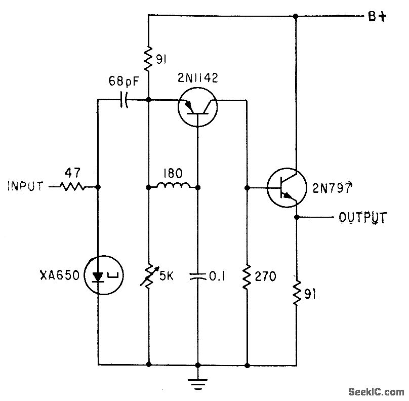
TUNNEL_DIODE_PULSER Signal_Processing Circuit Diagram
The study of what happens at the quantum scale.tunneling cannot be directly perceived.
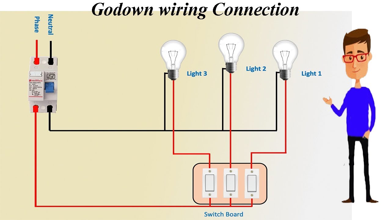
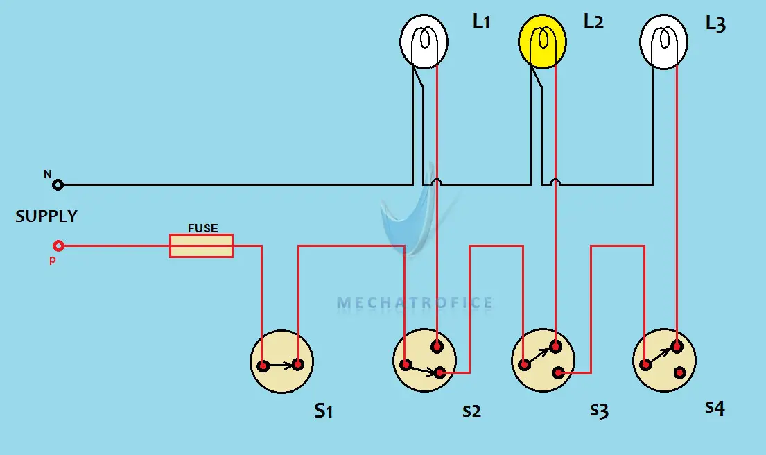
Tunnel circuit diagram. The tunnel circuit control the lamps in four ways as follow. Godown wiring circuit diagram and working. Energy diagram of tunnel diode for open circuit.
In the following diagram, the resistance of the connecting terminals of this diode & semiconductor material can be represented through ‘rs’ that is equivalent to the 5 ohms. Light bulb can be operate at a time. The tunnel diodes operating in negative resistance region are used in high speed applications such as in computers oscillators switching networks pulse generators and amplifiers where switching times are in the order of nanoseconds.
Circuit diagram of tunnel diode. The inductance of the connecting terminals ‘ls’ is almost equivalent to the 0.5nh. Godown wiring circuit diagram and its working.
Godown wiring circuit is needed in tunnel like structures, warehouses, long passages, big godowns having lots of rooms and different portions. This design is based on certain critical length of the tunnel. The circuit symbol of tunnel diode is shown in the below figure.
Instead of trapping only electrons, they suggested to trap electrons and holes on separate quantum dots which are coupled by a capacitor c c. It is necessary to balance the adaptability of the inside and outside luminance for the person entering or exiting the tunnel. Tunnel diode is a heavily doped diode which possesses high conductivity due to the higher concentration of impurity atoms.
To understand the phenomenon, particles attempting to travel across a potential barrier can be compared to a ball. Godown wiring uses to operate lamps/loads in a sequential manner, where only one load operates at a time. Advanced full instructions provided 13 hours 66,812.
The tunnel wiring circuit is used in structures. A tunnel/machine where the human can be sanitized the whole body by spraying the solution. It was the best choice to save electricity and energy consumption where only one load i.e.
Etc, where the light is only required for passage or it. The schematic symbol of tunnel diode is represented in the below diagram. As seen in the figure below, the fermi level is no more in the forbidden gap of the energy band for a highly doped tunnel diode.
We believe that the information given in this article is helpful for you for a better understanding of this project. ;7 $ ǿ s c ǿ u 1f %.i 5y'jw j ő @ s mc u 0 t o$ i %v0 , $ n$ 4a 0 ¯唦 k ~w1 j p fuu ) uj( 5 e n b )nㄼ0 wn% ;r2 ~ ϒ e ' gib lͯ kl%* bj^q6 2 e nhξ__ u 0 2 ez v v @q(b rr _ qexc. Tunnel lighting is necessary to solve the problem of abrupt adaptability of the environment inside the tunnel.
In this connection if a person switch bottom switch of stair and when he/she reached on top then if he switch the upper 2 way button then bulb will. The circuit diagram of the tunnel diode is shown below. The following image shows a typical spdt toggle switch with its terminals.
If the same air is being circulated in such a way that the wind tunnel does neither draw new air from the surrounding, nor return it into Its principle of operation is tunneling. This is all about the tunnel diode circuit with operations, circuit diagram and its applications.
Smart disinfection and sanitation tunnel. Gunn diodes these are similar to tunnel diodes in that they are made of materials such as gaas. We know that a anode is a positively charged electrode which attracts electrons whereas cathode is a negatively charged electrode which emits electrons.
The circuit diagram which shows the connection of sensor, relay and controller. Much of its understanding is shaped by the microscopic world, which classical mechanics cannot explain. The smart disinfection and sanitation tunnel is a demonstration of how it has been designed to provide maximum protection to people passing through the tunnel in around 15 seconds.
A wiring diagram is a simplified conventional photographic depiction of an electric circuit. It can disinfect a person fully in a time span of just 15 seconds. The tunnel diode circuit symbol is as shown below.
Tunnel wiring circuit is used in open ended corridors and short tunnels like structures. The tunnel circuit control the lamps in four ways as follow.

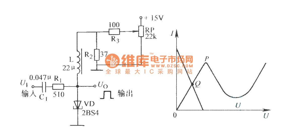
The tunnel diode circuit and its phase portrait Download

Singleelectron tunnel circuit consisting of tunnel

Diagram of the closedcircuit subsonic wind tunnel Sketch
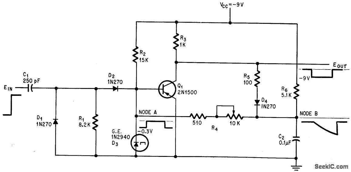
Tunnel diode monostable circuit Basic_Circuit Circuit

Godown Wiring Diagram With 5 Light Godown Wiring Diagram
TUNNEL_DIODE_GIVES_FAST_MONO_RECOV Basic_Circuit
Tunnel diode bistable circuit Basic_Circuit Circuit

Block diagram of an asynchronous pcircuit A
Basic Lamp Wiring Diagram Godown Wiring Diagram Tunnel


☑ Tunnel Diode Energy Band Diagram Explanation
Diagram of the closedcircuit subsonic wind tunnel Sketch
Godown Wiring Diagram With 5 Light Godown Wiring Diagram

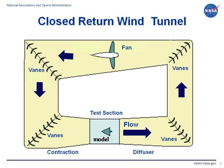
Closed Return Wind Tunnel
Godown Wiring Diagram With 5 Light Godown Wiring Diagram

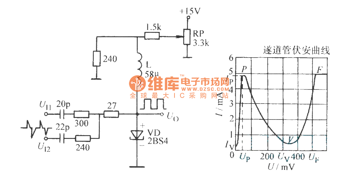
☑ Tunnel Diode Circuit Diagram
typical basement wiring diagram Wiring Diagram

Tunnel Diode Tunnel Diode Working And Operation In Detailed
Godown Wiring Diagram Electrical Gambarin.us Backup Gambar
Combined equivalent circuit of rectangular patch antenna