Universal Wiper Switch Wiring Diagram
Wiring diagram for windshield wiper motor zookastar. Universal wiring harness installation manual.
Universal Wiper Switch Wiring Diagram Drivenheisenberg

Terminals connected:) fully counterclockwise (off):
Universal wiper switch wiring diagram. When the purple wire is grounded the motor runs in high speed. A wiring diagram is a streamlined standard pictorial depiction of an electric circuit. On the schematic for the wiper switch is it showing a jumper wire going from no combination of wire swapping on the switch terminal gave me off.
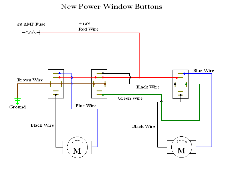
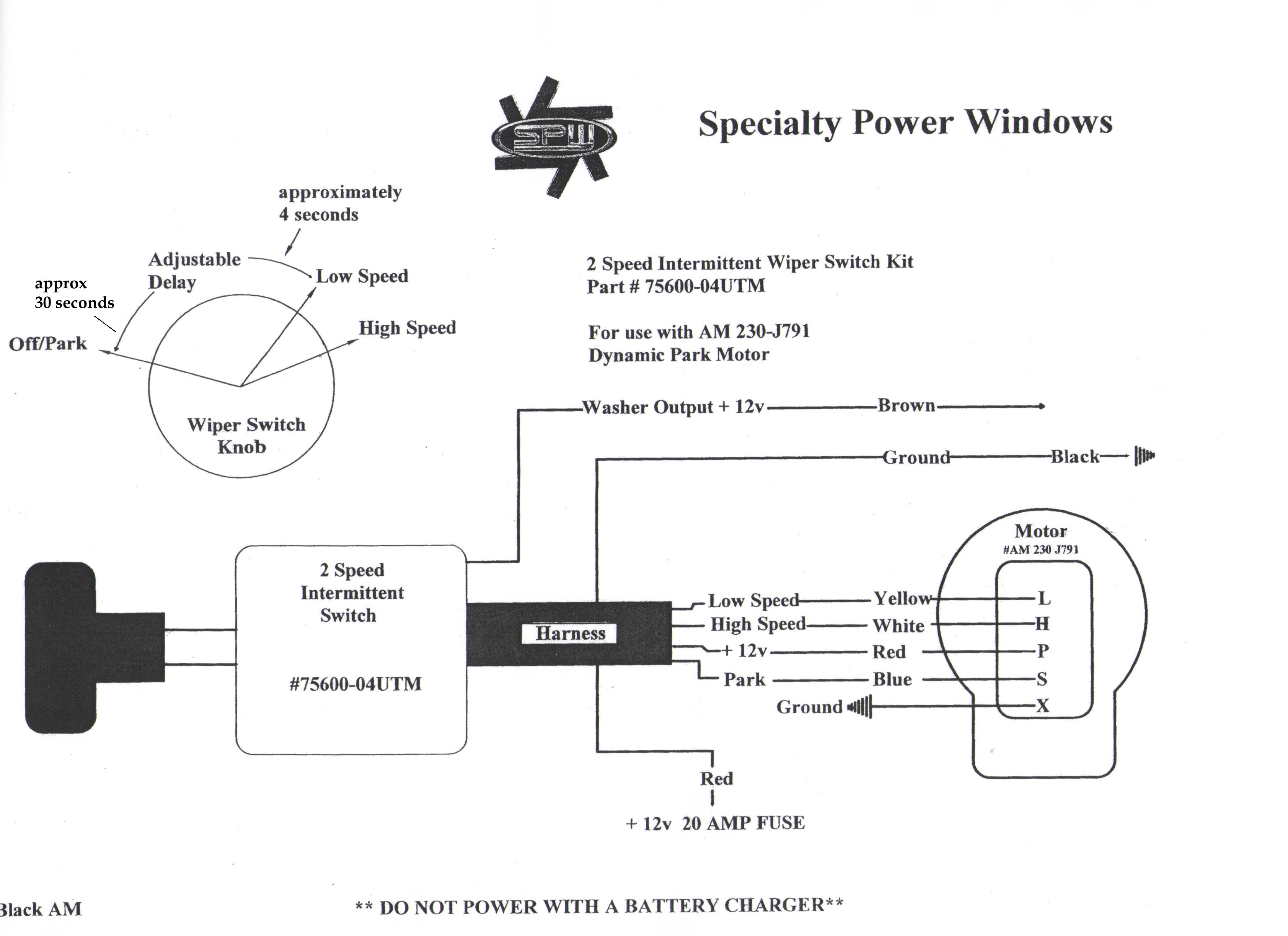
Below is a wiring diagram for a do it yourself 2 speed switch. Universal 12v timer relay providing a 5 sec delay for an intermittent wiper function. Joined jan 24 2008 387 posts.
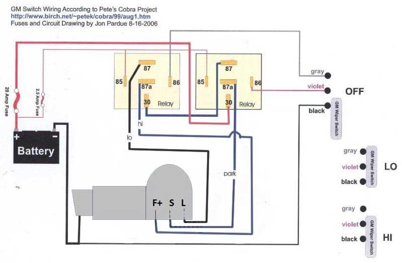
Refer to the attached diagram of a typical gm wiper motor and switch. Additionally the low speed coil is typically supplied by a red wire while the high speed coil is fed by a black wire. It shows the components of the circuit as simplified shapes, and the gift and signal contacts with the devices.
Slow speed as shown in the wiring diagram above and not the fast speed. Universal wiper switch wiring diagram here you are at our site this is images about universal wiper switch wiring diagram posted by benson fannie in universal category on sep 17 2019. What kind of wiring do i need for my wiper?
It shows the components of the circuit as simplified shapes, and the gift and signal contacts with the devices. A ground wire will then be wired from the 'b' terminal on the switch to a grounded location. The purple and gray wire are switched to ground to get low, high and park.
30a fuse for the wiper motor relays and wiper motor 15a fuse for the washer motor relay and washer motor 10a fuse for the low current board in the sjc to receive the washer signal from the mfs and provide ground to. Two way switching schematic wiring diagram (3 wire control). The harness connector is a 6 terminal female connector but only 4 terminals are used.
Painless performance limited warranty and return policy chassis harnesses, fuel injection harnesses and striker coldshot are covered under. Incorporates an output for supplying +12v to the wiper motor park switch which shorts the motor at the end of the wipe cycle, bringing the blades to an immediate stop in the 'park' position. 7) wire up the motor as shown in diagram #1 or #2.
When both wires are grounded the motor runs in low speed. Fj40 wiper motor wiring diagram. Fj40 wiper motor wiring diagram pirate 4×4.
1969 wipers wire assignments ih8mud forum. Brake light orange 12 volt feed to brake switch connect this wire to one side of your brake switch. The normal position corresponds to the switch.
Drive shaft & universal joints. Universal hot rod wiring diagram basic wiring diagram •. Cut off this connector if you don’t use the gm steering column or use a dash mounted ignition key switch (see the alternate ignition switch detail on the wiring diagram).
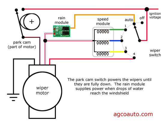
I have a diagram that shows: The four wires are generally power, low speed, high speed and auto park. When using this switch with the universal stainless wiper motor 911 23502 the switch will be wired from the s terminal on.
The two speed wiper switch can be used on any 1 speed motor. 3 way switch wiring diagram in 2019 diy home. Universal wiper switch wiring diagram exclusive wiring diagram universal horn on wiring diagram automotive wiring schematic windshield wiper motor diagram wiring schematic diagram painless performance 80121 pan80121 repl.
On a gm wiper motor the white wire is hot. Mopar wiper switch wiring diagram schematics wiring diagrams •. The 'h' and 'p' terminals will remain unused for this application.
Like the rear chassis harness or the wiper harness. Refer to the wiring diagram to see the positions of each wire in this connector (acc, bat2, ign wires). The only wire that doesn't seem to be getting power is the red one on the wiper motor.
Kit car, replica, wiper motor, wiring, tutorial When using this switch with the universal stainless wiper motor 911 23502 the switch will be wired from the s terminal on the motor to the l terminal on the switch. View our collection of helpful rocker switch wiring diagrams.
Yellow to #1 green to #2 red to #3 and then continue red wire to acc power source blue(white in your case) to #4 some wiper switches do not account for a ground connection as the wiper motor usually grounds itself to the mounting source. A ground wire will then be wired from the terminals on the switch numbered with '1', '2', '3', and '4' to a grounded location. The timer is activated from the wiper switch 'intermittent' position and closes the relay once every 5 seconds, sending power to the wiper motor.
4 Wire Wiper Motor Wiring Diagram Wiring Diagram Schemas
4 wire wiper motor wiring diagram

20 Unique Universal Wiper Switch Wiring Diagram
Ford Wiper Switch Wiring Diagram Database Wiring Diagram Sample
Alternative wiper switches?
Universal Wiper Switch Wiring Diagram General Wiring Diagram
GM column switch / universal wiper motor. Hot Rod Forum Hotrodders Bulletin Board
[DIAGRAM] How To Install A Wiper Motor Wiring Diagram FULL Version HD Quality Wiring Diagram
[VR_0414] John Deere Wiper Motor Wiring Diagram Schematic Wiring

Universal Wiper Switch Wiring Diagram Diagram For You

Universal Wiper Switch Wiring Diagram DEBATK12
Painless Wiring A Wiper Switch?

Universal Wiper Switch Wiring Diagram Atkinsjewelry
Universal Wiper Switch Wiring Diagram General Wiring Diagram

Universal Wiper Switch Wiring Diagram Diagram For You

Universal Wiper Switch Wiring Diagram General Wiring Diagram

Patent US4286200 Universal intermittent windshield wiper circuit Google Patents

4 Wire Wiper Motor Wiring Diagram Wiring Diagram Schemas

Cole Hersee Wiper Switch Wiring Diagram On Wiperwiring Stock Page Extraordinary To Electric
